适用产品和版本
- CloudEngine系列交换机V100R001C00或更高版本。
- USG5500系列产品V300R001版本。
- 如果需要了解软件版本与交换机具体型号的配套信息,请查看硬件中心。
组网需求
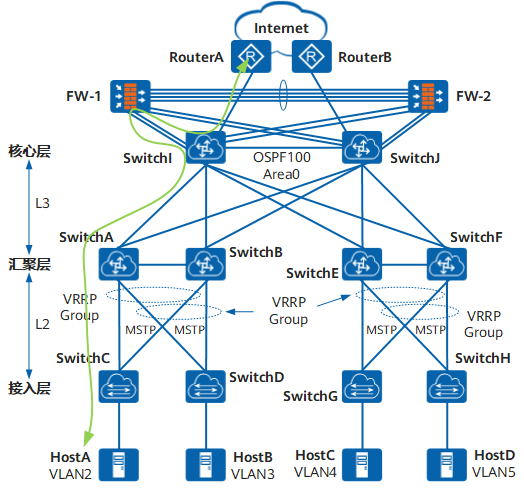
在数据中心场景中,采用接入层、汇聚层和核心层三层方式部署。用户希望:
- 考虑到业务的可靠性,接入层和汇聚层之间部署VRRP,在一条上行链路断开的时候,流量能切换到另外一条上行链路转发。
- 避免冗余备份链路导致的环网问题,消除接入层和汇聚层之间的环路。
- 核心层设备外挂防火墙,对业务流量提供安全过滤功能。
- 汇聚层和核心层部署OSPF协议实现三层互通。
| 设备 | VLAN及IP地址 | 接口编号 | 描述 |
|---|---|---|---|
| SwitchA | VLAN:2
IP地址:10.1.2.102/24 虚拟IP地址:10.1.2.100 |
10GE1/0/1 | TO-CE6800-SWITCHC |
| 10GE1/0/3 | TO-CE12800-SWITCHB | ||
| VLAN:3
IP地址:10.1.3.102/24 虚拟IP地址:10.1.3.100 |
10GE1/0/2 | TO-CE6800-SWITCHD | |
| 10GE1/0/3 | TO-CE12800-SWITCHB | ||
| VLAN:6
IP地址:10.1.6.102/24 |
10GE1/0/4 | TO-CE12800-SWITCHI | |
| VLAN:7
IP地址:10.1.7.102/24 |
10GE1/0/5 | TO-CE12800-SWITCHJ | |
| SwitchB | VLAN:2
IP地址:10.1.2.103/24 虚拟IP地址:10.1.2.100
|
10GE1/0/2 | TO-CE6800-SWITCHC |
| 10GE1/0/3 | TO-CE12800-SWITCHA | ||
| VLAN:3
IP地址:10.1.3.103/24 虚拟IP地址:10.1.3.100 |
10GE1/0/1 | TO-CE6800-SWITCHD | |
| 10GE1/0/3 | TO-CE12800-SWITCHA | ||
| VLAN:6
IP地址:10.1.6.103/24 |
10GE1/0/4 | TO-CE12800-SWITCHI | |
| VLAN:7
IP地址:10.1.7.103/24 |
10GE1/0/5 | TO-CE12800-SWITCHJ | |
| SwitchC | VLAN:2 | 10GE1/0/1 | TO-CE12800-SWITCHA |
| 10GE1/0/2 | TO-CE12800-SWITCHB | ||
| 10GE1/0/3 | TO-HOSTA | ||
| SwitchD | VLAN:3 | 10GE1/0/1 | TO-CE12800-SWITCHB |
| 10GE1/0/2 | TO-CE12800-SWITCHA | ||
| 10GE1/0/3 | TO-HOSTB | ||
| SwitchI | VLAN:6
IP地址:10.1.6.104/24 |
10GE1/0/1 | TO-CE12800-SWITCHA |
| 10GE1/0/2 | TO-CE12800-SWITCHB | ||
| 10GE1/0/3 | TO-CE12800-SWITCHE | ||
| 10GE1/0/4 | TO-CE12800-SWITCHF | ||
| VLAN:8
IP地址:10.1.8.104/24 |
10GE1/0/5 | TO-ROUTERA | |
| VLAN:9
IP地址:172.16.1.2/24 |
10GE1/0/6 | TO-FW-1 | |
| VLAN:10
IP地址:172.16.2.2/24 |
10GE1/0/7 | TO-FW-1 | |
| VLAN:11
IP地址:172.16.3.2/24 |
10GE1/0/8 | TO-FW-2 | |
| VLAN:12
IP地址:172.16.4.2/24 |
10GE1/0/9 | TO-FW-2 | |
| VLAN:13
IP地址:10.1.13.102/24 |
10GE1/0/14 | TO-CE12800-SWITCHJ | |
| SwitchJ | VLAN:7
IP地址:10.1.7.104/24 |
10GE1/0/1 | TO-CE12800-SWITCHA |
| 10GE1/0/2 | TO-CE12800-SWITCHB | ||
| 10GE1/0/3 | TO-CE12800-SWITCHE | ||
| 10GE1/0/4 | TO-CE12800-SWITCHF | ||
| VLAN:8
IP地址:10.1.8.105/24 |
10GE1/0/5 | TO-ROUTERB | |
| VLAN:9
IP地址:172.16.6.2/24 |
10GE1/0/6 | TO-FW-1 | |
| VLAN:10
IP地址:172.16.7.2/24 |
10GE1/0/7 | TO-FW-1 | |
| VLAN:11
IP地址:172.16.8.2/24 |
10GE1/0/8 | TO-FW-2 | |
| VLAN:12
IP地址:172.16.9.2/24 |
10GE1/0/9 | TO-FW-2 | |
| VLAN:13
IP地址:10.1.13.103/24 |
10GE1/0/14 | TO-CE12800-SWITCHI | |
| FW-1 | 172.16.1.1/24 | GE1/0/1 | TO-SWITCHI-Upstream |
| 172.16.2.1/24 | GE1/0/2 | TO-SWITCHI-Downstream | |
| 172.16.6.1/24 | GE1/0/3 | TO-SWITCHJ-Upstream | |
| 172.16.7.1/24 | GE1/0/4 | TO-SWITCHJ-Downstream | |
| 172.16.5.1/24 | Eth-Trunk1:GE2/0/0 | TO-FW-2-HRP | |
| Eth-Trunk1:GE2/0/1 | |||
| Eth-Trunk1:GE2/0/2 | |||
| Eth-Trunk1:GE2/0/3 | |||
| 172.16.100.1/24 | Loopback1 | NA | |
| 172.16.100.2/24 | Loopback2 | NA | |
| 172.16.100.3/24 | Loopback3 | NA | |
| 172.16.100.4/24 | Loopback4 | NA | |
| FW-2 | 172.16.8.1/24 | GE1/0/1 | TO-SWITCHJ-Upstream |
| 172.16.9.1/24 | GE1/0/2 | TO-SWITCHJ-Downstream | |
| 172.16.3.1/24 | GE1/0/3 | TO-SWITCHI-Upstream | |
| 172.16.4.1/24 | GE1/0/4 | TO-SWITCHI-Downstream | |
| 172.16.10.1/24 | Eth-Trunk1:GE2/0/0 | TO-FW-1-HRP | |
| Eth-Trunk1:GE2/0/1 | |||
| Eth-Trunk1:GE2/0/2 | |||
| Eth-Trunk1:GE2/0/3 | |||
| 172.16.100.1/24 | Loopback1 | NA | |
| 172.16.100.2/24 | Loopback2 | NA | |
| 172.16.100.3/24 | Loopback3 | NA | |
| 172.16.100.4/24 | Loopback4 | NA |
需求分析
- 通过在汇聚层设备SwitchA和SwitchB之间部署VRRP,实现链路冗余备份。
- 通过在汇聚层设备SwitchA、汇聚层设备SwitchB和接入层设备SwitchC之间部署MSTP,消除网络中的环路。
- 配置出口防火墙FW-1和FW-2双机热备,从核心层设备SwitchI或SwitchJ转发的流量经防火墙的安全策略处理,再分别流向数据中心或Internet。
- 通过在汇聚层设备SwitchA、汇聚层设备SwitchB、核心层设备SwitchI和SwitchJ之间部署OSPF,实现网络三层互通。
操作步骤
- 配置MSTP基本功能

只要两台设备的以下配置相同,这两台设备就属于同一个MST域。
- MST域的域名。
- 多生成树实例和VLAN的映射关系。
- MST域的修订级别。
- 配置SwitchA、SwitchB、SwitchC到域名为RG1的域内,创建实例MSTI1和实例MSTI2
# 配置汇聚层设备SwitchA的MST域。
<HUAWEI> system-view
[~HUAWEI] sysname SwitchA
[*HUAWEI] commit
[~SwitchA] stp region-configuration
[~SwitchA-mst-region] region-name RG1
[*SwitchA-mst-region] instance 1 vlan 2
[*SwitchA-mst-region] instance 2 vlan 3
[*SwitchA-mst-region] commit
[~SwitchA-mst-region] quit
# 配置汇聚层设备SwitchB的MST域。
<HUAWEI> system-view
[~HUAWEI] sysname SwitchB
[*HUAWEI] commit
[~SwitchB] stp region-configuration
[~SwitchB-mst-region] region-name RG1
[*SwitchB-mst-region] instance 1 vlan 2
[*SwitchB-mst-region] instance 2 vlan 3
[*SwitchB-mst-region] commit
[~SwitchB-mst-region] quit
# 配置接入层设备SwitchC的MST域。
<HUAWEI> system-view
[~HUAWEI] sysname SwitchC
[*HUAWEI] commit
[~SwitchC] stp region-configuration
[~SwitchC-mst-region] region-name RG1
[*SwitchC-mst-region] instance 1 vlan 2
[*SwitchC-mst-region] instance 2 vlan 3
[*SwitchC-mst-region] commit
[~SwitchC-mst-region] quit
# 配置接入层设备SwitchD的MST域。
<HUAWEI> system-view
[~HUAWEI] sysname SwitchD
[*HUAWEI] commit
[~SwitchD] stp region-configuration
[~SwitchD-mst-region] region-name RG1
[*SwitchD-mst-region] instance 1 vlan 2
[*SwitchD-mst-region] instance 2 vlan 3
[*SwitchD-mst-region] commit
[~SwitchD-mst-region] quit
- 在域RG1内,配置MSTI1与MSTI2的根桥与备份根桥
- 配置MSTI1的根桥与备份根桥
# 配置汇聚层设备SwitchA为MSTI1的根桥。
[~SwitchA] stp instance 1 root primary
[*SwitchA] commit
# 配置汇聚层设备SwitchB为MSTI1的备份根桥。
[~SwitchB] stp instance 1 root secondary
[*SwitchB] commit
- 配置MSTI2的根桥与备份根桥
# 配置汇聚层设备SwitchB为MSTI2的根桥。
[~SwitchB] stp instance 2 root primary
[*SwitchB] commit
# 配置汇聚层设备SwitchA为MSTI2的备份根桥。
[~SwitchA] stp instance 2 root secondary
[*SwitchA] commit
- 配置MSTI1的根桥与备份根桥
- 配置实例MSTI1和MSTI2中将要被阻塞端口的路径开销值大于缺省值
- 端口路径开销值取值范围由路径开销计算方法决定,这里选择使用华为私有计算方法为例,配置实例MSTI1和MSTI2中将被阻塞端口的路径开销值为20000。
- 同一网络内所有交换设备的端口路径开销应使用相同的计算方法。
# 配置汇聚层设备SwitchA的端口路径开销的计算方法为华为私有计算方法。
[~SwitchA] stp pathcost-standard legacy
[*SwitchA] commit
# 配置汇聚层设备SwitchB的端口路径开销的计算方法为华为的私有计算方法。
[~SwitchB] stp pathcost-standard legacy
[*SwitchB] commit
# 配置接入层设备SwitchC的端口路径开销的计算方法为华为的私有计算方法,将端口10GE1/0/2在实例MSTI1中的路径开销值配置为20000。
[~SwitchC] stp pathcost-standard legacy
[*SwitchC] interface 10ge 1/0/2
[*SwitchC-10GE1/0/2] description TO-CE12800-SWITCHB
[*SwitchC-10GE1/0/2] stp instance 1 cost 20000
[*SwitchC-10GE1/0/2] commit
[~SwitchC-10GE1/0/2] quit
# 配置接入层设备SwitchD的端口路径开销的计算方法为华为的私有计算方法,将端口10GE1/0/2在实例MSTI2中的路径开销值配置为20000。
[~SwitchD] stp pathcost-standard legacy
[*SwitchD] interface 10ge 1/0/2
[*SwitchD-10GE1/0/2] description TO-CE12800-SWITCHA
[*SwitchD-10GE1/0/2] stp instance 2 cost 20000
[*SwitchD-10GE1/0/2] commit
[~SwitchD-10GE1/0/2] quit
- 使能MSTP,实现破除环路
设备上MSTP功能默认使能。
- 设备全局使能MSTP
# 在汇聚层设备SwitchA上启动MSTP。
[~SwitchA] stp enable
[*SwitchA] commit
# 在汇聚层设备SwitchB上启动MSTP。
[~SwitchB] stp enable
[*SwitchB] commit
# 在接入层设备SwitchC上启动MSTP。
[~SwitchC] stp enable
[*SwitchC] commit
# 在接入层设备SwitchD上启动MSTP。
[~SwitchD] stp enable
[*SwitchD] commit
- 将与Host相连的端口配置为边缘端口
# 配置接入层设备SwitchC端口10GE1/0/3为边缘端口。
[~SwitchC] interface 10ge 1/0/3
[*SwitchC-10GE1/0/3] description TO-HOSTA
[*SwitchC-10GE1/0/3] stp edged-port enable
[*SwitchC-10GE1/0/3] commit
[~SwitchC-10GE1/0/3] quit
# 配置接入层设备SwitchD端口10GE1/0/3为边缘端口。
[~SwitchD] interface 10ge 1/0/3
[*SwitchD-10GE1/0/3] description TO-HOSTB
[*SwitchD-10GE1/0/3] stp edged-port enable
[*SwitchD-10GE1/0/3] commit
[~SwitchD-10GE1/0/3] quit
- 设备全局使能MSTP
- 配置保护功能,如在各实例的根桥设备的指定端口配置根保护功能
# 在汇聚层设备SwitchA端口10GE1/0/1上启动根保护。
[~SwitchA] interface 10ge 1/0/1
[~SwitchA-10GE1/0/1] description TO-CE6800-SWITCHC
[*SwitchA-10GE1/0/1] stp root-protection
[*SwitchA-10GE1/0/1] commit
[~SwitchA-10GE1/0/1] quit
# 在汇聚层设备SwitchB端口10GE1/0/1上启动根保护。
[~SwitchB] interface 10ge 1/0/1
[~SwitchB-10GE1/0/1] description TO-CE6800-SWITCHD
[*SwitchB-10GE1/0/1] stp root-protection
[*SwitchB-10GE1/0/1] commit
[~SwitchB-10GE1/0/1] quit
- 配置处于环网中的设备的二层转发功能
- 在交换设备SwitchA、SwitchB、SwitchC上创建VLAN2~3
# 在汇聚层设备SwitchA上创建VLAN2~3。
[~SwitchA] vlan batch 2 to 3# 在汇聚层设备SwitchB上创建VLAN2~3。
[~SwitchB] vlan batch 2 to 3# 在接入层设备SwitchC上创建VLAN2。
[~SwitchC] vlan batch 2# 在接入层设备SwitchD上创建VLAN3。
[~SwitchD] vlan batch 3 - 将交换设备上接入环路中的端口加入VLAN
# 将汇聚层设备SwitchA端口10GE1/0/1加入VLAN。
[~SwitchA] interface 10ge 1/0/1
[~SwitchA-10GE1/0/1] port link-type trunk
[*SwitchA-10GE1/0/1] undo port trunk allow-pass vlan 1
[*SwitchA-10GE1/0/1] port trunk allow-pass vlan 2
[*SwitchA-10GE1/0/1] commit
[~SwitchA-10GE1/0/1] quit
# 将汇聚层设备SwitchA端口10GE1/0/2加入VLAN。
[~SwitchA] interface 10ge 1/0/2
[~SwitchA-10GE1/0/2] description TO-CE6800-SWITCHD
[*SwitchA-10GE1/0/2] port link-type trunk
[*SwitchA-10GE1/0/2] port trunk allow-pass vlan 3
[*SwitchA-10GE1/0/2] commit
[~SwitchA-10GE1/0/2] quit
# 将汇聚层设备SwitchA端口10GE1/0/3加入VLAN。
[~SwitchA] interface 10ge 1/0/3
[~SwitchA-10GE1/0/3] description TO-CE12800-SWITCHB
[*SwitchA-10GE1/0/3] port link-type trunk
[*SwitchA-10GE1/0/3] undo port trunk allow-pass vlan 1
[*SwitchA-10GE1/0/3] port trunk allow-pass vlan 2 to 3
[*SwitchA-10GE1/0/3] commit
[~SwitchA-10GE1/0/3] quit
# 将汇聚层设备SwitchB端口10GE1/0/1加入VLAN。
[~SwitchB] interface 10ge 1/0/1
[~SwitchB-10GE1/0/1] port link-type trunk
[*SwitchB-10GE1/0/1] undo port trunk allow-pass vlan 1
[*SwitchB-10GE1/0/1] port trunk allow-pass vlan 3
[*SwitchB-10GE1/0/1] commit
[~SwitchB-10GE1/0/1] quit
# 将汇聚层设备SwitchB端口10GE1/0/2加入VLAN。
[~SwitchB] interface 10ge 1/0/2
[~SwitchB-10GE1/0/2] description TO-CE6800-SWITCHC
[*SwitchB-10GE1/0/2] port link-type trunk
[*SwitchB-10GE1/0/2] undo port trunk allow-pass vlan 1
[*SwitchB-10GE1/0/2] port trunk allow-pass vlan 2
[*SwitchB-10GE1/0/2] commit
[~SwitchB-10GE1/0/2] quit
# 将汇聚层设备SwitchB端口10GE1/0/3加入VLAN。
[~SwitchB] interface 10ge 1/0/3
[~SwitchB-10GE1/0/3] description TO-CE12800-SWITCHA
[*SwitchB-10GE1/0/3] port link-type trunk
[*SwitchB-10GE1/0/3] undo port trunk allow-pass vlan 1
[*SwitchB-10GE1/0/3] port trunk allow-pass vlan 2 to 3
[*SwitchB-10GE1/0/3] commit
[~SwitchB-10GE1/0/3] quit
# 将接入层设备SwitchC端口10GE1/0/1加入VLAN。
[~SwitchC] interface 10ge 1/0/1
[~SwitchC-10GE1/0/1] description TO-CE12800-SWITCHA
[*SwitchC-10GE1/0/1] port link-type trunk
[*SwitchC-10GE1/0/1] undo port trunk allow-pass vlan 1
[*SwitchC-10GE1/0/1] port trunk allow-pass vlan 2
[*SwitchC-10GE1/0/1] commit
[~SwitchC-10GE1/0/1] quit
# 将接入层设备SwitchC端口10GE1/0/2加入VLAN。
[~SwitchC] interface 10ge 1/0/2
[~SwitchC-10GE1/0/2] port link-type trunk
[*SwitchC-10GE1/0/2] undo port trunk allow-pass vlan 1
[*SwitchC-10GE1/0/2] port trunk allow-pass vlan 2
[*SwitchC-10GE1/0/2] commit
[~SwitchC-10GE1/0/2] quit
# 将接入层设备SwitchC端口10GE1/0/3加入VLAN。
[~SwitchC] interface 10ge 1/0/3
[~SwitchC-10GE1/0/3] port link-type access
[*SwitchC-10GE1/0/3] port default vlan 2
[*SwitchC-10GE1/0/3] commit
[~SwitchC-10GE1/0/3] quit
# 将接入层设备SwitchD端口10GE1/0/1加入VLAN。
[~SwitchD] interface 10ge 1/0/1
[~SwitchD-10GE1/0/1] description TO-CE12800-SWITCHB
[*SwitchD-10GE1/0/1] port link-type trunk
[*SwitchD-10GE1/0/1] undo port trunk allow-pass vlan 1
[*SwitchD-10GE1/0/1] port trunk allow-pass vlan 3
[*SwitchD-10GE1/0/1] commit
[~SwitchD-10GE1/0/1] quit
# 将接入层设备SwitchD端口10GE1/0/2加入VLAN。
[~SwitchD] interface 10ge 1/0/2
[~SwitchD-10GE1/0/2] port link-type trunk
[*SwitchD-10GE1/0/2] undo port trunk allow-pass vlan 1
[*SwitchD-10GE1/0/2] port trunk allow-pass vlan 3
[*SwitchD-10GE1/0/2] commit
[~SwitchD-10GE1/0/2] quit
# 将接入层设备SwitchD端口10GE1/0/3加入VLAN。
[~SwitchD] interface 10ge 1/0/3
[~SwitchD-10GE1/0/3] port link-type access
[*SwitchD-10GE1/0/3] port default vlan 3
[*SwitchD-10GE1/0/3] commit
[~SwitchD-10GE1/0/3] quit
- 在交换设备SwitchA、SwitchB、SwitchC上创建VLAN2~3
- 配置VRRP备份组
# 在汇聚层设备SwitchA和SwitchB上创建VRRP备份组1,配置SwitchA的优先级为120,抢占延时为20秒,作为Master设备;SwitchB的优先级为缺省值,作为Backup设备。
[~SwitchA] interface vlanif 2
[*SwitchA-Vlanif2] vrrp vrid 1 virtual-ip 10.1.2.100
[*SwitchA-Vlanif2] vrrp vrid 1 priority 120
[*SwitchA-Vlanif2] vrrp vrid 1 preempt-mode timer delay 20
[*SwitchA-Vlanif2] commit
[~SwitchA-Vlanif2] quit
[~SwitchB] interface vlanif 2
[*SwitchB-Vlanif2] vrrp vrid 1 virtual-ip 10.1.2.100
[*SwitchB-Vlanif2] commit
[~SwitchB-Vlanif2] quit
# 在汇聚层设备SwitchA和SwitchB上创建VRRP备份组2,配置SwitchB的优先级为120,抢占延时为20秒,作为Master设备;SwitchA的优先级为缺省值,作为Backup设备。
[~SwitchB] interface vlanif 3
[*SwitchB-Vlanif3] vrrp vrid 2 virtual-ip 10.1.3.100
[*SwitchB-Vlanif3] vrrp vrid 2 priority 120
[*SwitchB-Vlanif3] vrrp vrid 2 preempt-mode timer delay 20
[*SwitchB-Vlanif3] commit
[~SwitchB-Vlanif3] quit
[~SwitchA] interface vlanif 3
[*SwitchA-Vlanif3] vrrp vrid 2 virtual-ip 10.1.3.100
[*SwitchA-Vlanif3] commit
[~SwitchA-Vlanif3] quit
# 配置主机HostA的缺省网关为备份组1的虚拟IP地址10.1.2.100,配置主机HostB的缺省网关为备份组2的虚拟IP地址10.1.3.100。
- 配置设备间的网络互连
# 配置设备各接口的IP地址,以汇聚层设备SwitchA为例。SwitchB、SwitchI和SwitchJ的配置与之类似,详见配置文件。
[~SwitchA] vlan batch 6 7
[*SwitchA] interface 10ge 1/0/4
[*SwitchA-10GE1/0/4] description TO-CE12800-SWITCHI
[*SwitchA-10GE1/0/4] port link-type trunk
[*SwitchA-10GE1/0/4] undo port trunk allow-pass vlan 1
[*SwitchA-10GE1/0/4] port trunk allow-pass vlan 6
[*SwitchA-10GE1/0/4] quit
[*SwitchA] interface 10ge 1/0/5
[*SwitchA-10GE1/0/5] description TO-CE12800-SWITCHJ
[*SwitchA-10GE1/0/5] port link-type trunk
[*SwitchA-10GE1/0/5] undo port trunk allow-pass vlan 1
[*SwitchA-10GE1/0/5] port trunk allow-pass vlan 7
[*SwitchA-10GE1/0/5] quit
[*SwitchA] interface vlanif 2
[*SwitchA-Vlanif2] ip address 10.1.2.102 24
[*SwitchA-Vlanif2] quit
[*SwitchA] interface vlanif 3
[*SwitchA-Vlanif3] ip address 10.1.3.102 24
[*SwitchA-Vlanif3] quit
[*SwitchA] interface vlanif 6
[*SwitchA-Vlanif6] ip address 10.1.6.102 24
[*SwitchA-Vlanif6] quit
[*SwitchA] interface vlanif 7
[*SwitchA-Vlanif7] ip address 10.1.7.102 24
[*SwitchA-Vlanif7] quit
[*SwitchA] commit
# 配置汇聚层设备SwitchA、汇聚层设备SwitchB、核心层设备SwitchI、核心层设备SwitchJ和出口路由器间采用OSPF协议进行互连。
[~SwitchA] ospf 1
[*SwitchA-ospf-1] area 0
[*SwitchA-ospf-1-area-0.0.0.0] network 10.1.2.0 0.0.0.255
[*SwitchA-ospf-1-area-0.0.0.0] network 10.1.3.0 0.0.0.255
[*SwitchA-ospf-1-area-0.0.0.0] network 10.1.6.0 0.0.0.255
[*SwitchA-ospf-1-area-0.0.0.0] network 10.1.7.0 0.0.0.255
[*SwitchA-ospf-1-area-0.0.0.0] quit
[*SwitchA-ospf-1] quit
[*SwitchA] commit
- 配置防火墙。
配置FW-1和FW-2进行双机热备,从SwitchI、SwitchJ转发的报文经FW-1或FW-2的安全策略处理,再分别流向数据中心或Internet。
FW-1和FW-2进行负载分担,均同时转发流量,当一台FW故障时,业务可以平滑切换到另一台FW。
以下FW-1和FW-2以华为USG统一安全网关为例,介绍FW双机热备负载分担配置步骤。
- 配置攻击防范。
本举例中的攻击防范阈值仅供参考,实际配置时,请管理员根据网络实际流量进行配置。
HRP_M[FW-1] firewall defend syn-flood enable
HRP_M[FW-1] firewall defend syn-flood enable
HRP_M[FW-1] firewall defend syn-flood zone untrust max-rate 20000
HRP_M[FW-1] firewall defend udp-flood enable
HRP_M[FW-1] firewall defend udp-flood zone untrust max-rate 1500
HRP_M[FW-1] firewall defend icmp-flood enable
HRP_M[FW-1] firewall defend icmp-flood zone untrust max-rate 20000
HRP_M[FW-1] firewall blacklist enable
HRP_M[FW-1] firewall defend ip-sweep enable
HRP_M[FW-1] firewall defend ip-sweep max-rate 4000
HRP_M[FW-1] firewall defend port-scan enable
HRP_M[FW-1] firewall defend port-scan max-rate 4000
HRP_M[FW-1] firewall defend ip-fragment enable
HRP_M[FW-1] firewall defend ip-spoofing enable
- 配置攻击防范。
- 配置策略路由将所有流经核心层设备SwitchI和SwitchJ的流量通过策略路由重定向到防火墙,防火墙对流量进行过滤。
# 以核心层设备SwitchI的配置为例,核心层设备SwitchJ配置与之类似,详见配置文件。
[~SwitchI] acl 3001
[*SwitchI-acl4-advance-3001] rule 5 permit ip source 10.1.2.0 24
[*SwitchI-acl4-advance-3001] rule 10 permit ip source 10.1.3.0 24
[*SwitchI-acl4-advance-3001] rule 15 permit ip source 10.1.4.0 24
[*SwitchI-acl4-advance-3001] rule 20 permit ip source 10.1.5.0 24
[*SwitchI-acl4-advance-3001] commit
[~SwitchI-acl4-advance-3001] quit
[~SwitchI] traffic classifier c1
[*SwitchI-classifier-c1] if-match acl 3001
[*SwitchI-classifier-c1] quit
[*SwitchI] commit
[~SwitchI] traffic behavior b1
[*SwitchI-behavior-b1] redirect load-balance nexthop 172.16.100.1 172.16.100.3
[*SwitchI-behavior-b1] quit
[*SwitchI] commit
[~SwitchI] traffic policy p1
[*SwitchI-trafficpolicy-p1] classifier c1 behavior b1
[*SwitchI-trafficpolicy-p1] quit
[*SwitchI] commit
[~SwitchI] interface 10ge 1/0/1
[~SwitchI-10GE1/0/1] traffic-policy p1 inbound
[*SwitchI-10GE1/0/1] quit
[*SwitchI] commit
[~SwitchI] interface 10ge 1/0/2
[~SwitchI-10GE1/0/2] traffic-policy p1 inbound
[*SwitchI-10GE1/0/2] quit
[*SwitchI] commit
[~SwitchI] interface 10ge 1/0/3
[~SwitchI-10GE1/0/3] traffic-policy p1 inbound
[*SwitchI-10GE1/0/3] quit
[*SwitchI] commit
[~SwitchI] interface 10ge 1/0/4
[~SwitchI-10GE1/0/4] traffic-policy p1 inbound
[*SwitchI-10GE1/0/4] quit
[*SwitchI] commit
[~SwitchI] interface 10ge 1/0/14
[~SwitchI-10GE1/0/14] traffic-policy p1 inbound
[*SwitchI-10GE1/0/14] quit
[*SwitchI] commit
[~SwitchI] acl 3003
[*SwitchI-acl4-advance-3003] rule 5 permit ip destination 10.1.2.0 24
[*SwitchI-acl4-advance-3003] rule 10 permit ip destination 10.1.3.0 24
[*SwitchI-acl4-advance-3003] rule 15 permit ip destination 10.1.4.0 24
[*SwitchI-acl4-advance-3003] rule 20 permit ip destination 10.1.5.0 24
[*SwitchI-acl4-advance-3003] commit
[~SwitchI-acl4-advance-3003] quit
[~SwitchI] traffic classifier c3
[*SwitchI-classifier-c3] if-match acl 3003
[*SwitchI-classifier-c3] quit
[*SwitchI] commit
[~SwitchI] traffic behavior b3
[*SwitchI-behavior-b3] redirect load-balance nexthop 172.16.100.2 172.16.100.4
[*SwitchI-behavior-b3] quit
[*SwitchI] commit
[~SwitchI] traffic policy p2
[*SwitchI-trafficpolicy-p2] classifier c3 behavior b3
[*SwitchI-trafficpolicy-p2] quit
[*SwitchI] commit
[~SwitchI] interface 10ge 1/0/5
[~SwitchI-10GE1/0/5] traffic-policy p2 inbound
[*SwitchI-10GE1/0/5] quit
[*SwitchI] commit
验证
- 完成上述配置后,在汇聚层设备SwitchA上执行display vrrp命令,可以看到SwitchA在备份组1中作为Master设备,在备份组2中作为Backup设备。
<SwitchA> display vrrp verbose Vlanif2 | Virtual Router 1 State : Master Virtual IP : 10.1.2.100 Master IP : 10.1.2.102 PriorityRun : 120 PriorityConfig : 120 MasterPriority : 120 Preempt : YES Delay Time : 20 s Remain : -- TimerRun : 1 s TimerConfig : 1 s Auth Type : NONE Virtual MAC : 0000-5e00-0101 Check TTL : YES Config Type : normal-vrrp Create Time : 2013-05-11 11:39:18 Last Change Time : 2013-05-26 11:38:58 Vlanif3 | Virtual Router 2 State : Backup Virtual IP : 10.1.3.100 Master IP : 10.1.3.103 PriorityRun : 100 PriorityConfig : 100 MasterPriority : 120 Preempt : YES Delay Time : 0 s Remain : -- TimerRun : 1 s TimerConfig : 1 s Auth type : NONE Virtual MAC : 0000-5e00-0102 Check TTL : YES Config Type : normal-vrrp Create Time : 2013-05-11 11:40:18 Last Change Time : 2013-05-26 11:48:58 - 在汇聚层设备SwitchB上执行display vrrp命令,可以看到SwitchB在备份组1中作为Backup设备,在备份组2中作为Master设备。
<SwitchB> display vrrp verbose
  Vlanif2 | Virtual Router 1
    State : Backup
    Virtual IP : 10.1.2.100
    Master IP : 10.1.2.102
    PriorityRun : 100
    PriorityConfig : 100
    MasterPriority : 120
    Preempt : YES   Delay Time : 0 s   Remain : --
    TimerRun : 1 s
    TimerConfig : 1 s
    Auth Type : NONE
    Virtual MAC : 0000-5e00-0101
    Check TTL : YES
    Config Type : normal-vrrp
    Create Time : 2012-05-11 11:39:18
    Last Change Time : 2012-05-26 11:38:58

  Vlanif3 | Virtual Router 2
    State : Master
    Virtual IP : 10.1.3.100
    Master IP : 10.1.3.103
    PriorityRun : 120
    PriorityConfig : 120
    MasterPriority : 120
    Preempt : YES   Delay Time : 20 s   Remain : --
    TimerRun : 1 s
    TimerConfig : 1 s
    Auth type : NONE
    Virtual MAC : 0000-5e00-0102
    Check TTL : YES
    Config Type : normal-vrrp
    Create Time : 2012-05-11 11:40:18
    Last Change Time : 2012-05-26 11:48:58
配置文件
- 汇聚层设备SwitchA的配置文件
#
sysname SwitchA
#
vlan batch 2 to 3 6 to 7
#
stp instance 1 root primary
stp instance 2 root secondary
stp pathcost-standard legacy
#
stp region-configuration
 region-name RG1
 instance 1 vlan 2
 instance 2 vlan 3
#
interface Vlanif2
 ip address 10.1.2.102 255.255.255.0
 vrrp vrid 1 virtual-ip 10.1.2.100
 vrrp vrid 1 priority 120
 vrrp vrid 1 preempt timer delay 20
#
interface Vlanif3
 ip address 10.1.3.102 255.255.255.0
 vrrp vrid 2 virtual-ip 10.1.3.100
#
interface Vlanif6
 ip address 10.1.6.102 255.255.255.0
#
interface Vlanif7
 ip address 10.1.7.102 255.255.255.0
#
interface 10GE1/0/1
 description TO-CE6800-SWITCHC
 port link-type trunk
 undo port trunk allow-pass vlan 1
 port trunk allow-pass vlan 2
 stp root-protection
#
interface 10GE1/0/2
 description TO-CE6800-SWITCHD
 port link-type trunk
 undo port trunk allow-pass vlan 1
 port trunk allow-pass vlan 3
#
interface 10GE1/0/3
 description TO-CE12800-SWITCHB
 port link-type trunk
 undo port trunk allow-pass vlan 1
 port trunk allow-pass vlan 2 to 3
#
interface 10GE1/0/4
 description TO-CE12800-SWITCHI
 port link-type trunk
 undo port trunk allow-pass vlan 1
 port trunk allow-pass vlan 6
#
interface 10GE1/0/5
 description TO-CE12800-SWITCHJ
 port link-type trunk
 undo port trunk allow-pass vlan 1
 port trunk allow-pass vlan 7
#
ospf 1
 area 0.0.0.0
  network 10.1.2.0 0.0.0.255
  network 10.1.3.0 0.0.0.255
  network 10.1.6.0 0.0.0.255
  network 10.1.7.0 0.0.0.255
#
return
- 汇聚层设备SwitchB的配置文件
#
sysname SwitchB
#
vlan batch 2 to 3 6 to 7
#
stp instance 1 root secondary
stp instance 2 root primary
stp pathcost-standard legacy
#
stp region-configuration
 region-name RG1
 instance 1 vlan 2
 instance 2 vlan 3
#
interface Vlanif2
 ip address 10.1.2.103 255.255.255.0
 vrrp vrid 1 virtual-ip 10.1.2.100
#
interface Vlanif3
 ip address 10.1.3.103 255.255.255.0
 vrrp vrid 2 virtual-ip 10.1.3.100
 vrrp vrid 2 priority 120
 vrrp vrid 2 preempt timer delay 20
#
interface Vlanif6
 ip address 10.1.6.103 255.255.255.0
#
interface Vlanif7
 ip address 10.1.7.103 255.255.255.0
#
interface 10GE1/0/1
 description TO-CE6800-SWITCHD
 port link-type trunk
 undo port trunk allow-pass vlan 1
 port trunk allow-pass vlan 3
 stp root-protection
#
interface 10GE1/0/2
 description TO-CE6800-SWITCHC
 port link-type trunk
 undo port trunk allow-pass vlan 1
 port trunk allow-pass vlan 2
#
interface 10GE1/0/3
 description TO-CE12800-SWITCHA
 port link-type trunk
 undo port trunk allow-pass vlan 1
 port trunk allow-pass vlan 2 to 3
#
interface 10GE1/0/4
 description TO-CE12800-SWITCHI
 port link-type trunk
 undo port trunk allow-pass vlan 1
 port trunk allow-pass vlan 6
#
interface 10GE1/0/5
 description TO-CE12800-SWITCHJ
 port link-type trunk
 undo port trunk allow-pass vlan 1
 port trunk allow-pass vlan 7
#
ospf 1
 area 0.0.0.0
  network 10.1.2.0 0.0.0.255
  network 10.1.3.0 0.0.0.255
  network 10.1.6.0 0.0.0.255
  network 10.1.7.0 0.0.0.255
#
return
- 接入层设备SwitchC的配置文件
#
sysname SwitchC
#
vlan batch 2
#
stp pathcost-standard legacy
#
stp region-configuration
 region-name RG1
 instance 1 vlan 2
 instance 2 vlan 3
#
interface 10GE1/0/1
 description TO-CE12800-SWITCHA
 port link-type trunk
 undo port trunk allow-pass vlan 1
 port trunk allow-pass vlan 2
#
interface 10GE1/0/2
 description TO-CE12800-SWITCHB
 port link-type trunk
 undo port trunk allow-pass vlan 1
 port trunk allow-pass vlan 2
 stp instance 1 cost 20000
#
interface 10GE1/0/3
 description TO-HOSTA
 port default vlan 2
 stp disable
#
return
- 接入层设备SwitchD的配置文件
#
sysname SwitchD
#
vlan batch 3
#
stp pathcost-standard legacy
#
stp region-configuration
 region-name RG1
 instance 1 vlan 2
 instance 2 vlan 3
#
interface 10GE1/0/1
 description TO-CE12800-SWITCHB
 port link-type trunk
 undo port trunk allow-pass vlan 1
 port trunk allow-pass vlan 3
#
interface 10GE1/0/2
 description TO-CE12800-SWITCHA
 port link-type trunk
 undo port trunk allow-pass vlan 1
 port trunk allow-pass vlan 3
 stp instance 2 cost 20000
#
interface 10GE1/0/3
 description TO-HOSTB
 port default vlan 3
 stp disable
#
return
- 核心层设备SwitchI的配置文件
#
sysname SwitchI
#
vlan batch 6 8 to 13
#
acl number 3001
 rule 5 permit ip source 10.1.2.0 0.0.0.255
 rule 10 permit ip source 10.1.3.0 0.0.0.255
 rule 15 permit ip source 10.1.4.0 0.0.0.255
 rule 20 permit ip source 10.1.5.0 0.0.0.255
#
acl number 3003
 rule 5 permit ip destination 10.1.2.0 0.0.0.255
 rule 10 permit ip destination 10.1.3.0 0.0.0.255
 rule 15 permit ip destination 10.1.4.0 0.0.0.255
 rule 20 permit ip destination 10.1.5.0 0.0.0.255
#
traffic classifier c1 type or
 if-match acl 3001
#
traffic classifier c3 type or
 if-match acl 3003
#
traffic behavior b1
 redirect load-balance nexthop 172.16.100.1 172.16.100.3
#
traffic behavior b3
 redirect load-balance nexthop 172.16.100.2 172.16.100.4
#
traffic policy p1
 classifier c1 behavior b1 precedence 5
#
traffic policy p2
 classifier c3 behavior b3 precedence 5
#
interface Vlanif6
 ip address 10.1.6.104 255.255.255.0
#
interface Vlanif8
 ip address 10.1.8.104 255.255.255.0
#
interface Vlanif9
 ip address 172.16.1.2 255.255.255.0
#
interface Vlanif10
 ip address 172.16.2.2 255.255.255.0
#
interface Vlanif11
 ip address 172.16.3.2 255.255.255.0
#
interface Vlanif12
 ip address 172.16.4.2 255.255.255.0
#
interface Vlanif13
 ip address 10.1.13.102 255.255.255.0
#
interface 10GE1/0/1
 description TO-CE12800-SWITCHA
 port link-type trunk
 undo port trunk allow-pass vlan 1
 port trunk allow-pass vlan 6
 traffic-policy p1 inbound
#
interface 10GE1/0/2
 description TO-CE12800-SWITCHB
 port link-type trunk
 undo port trunk allow-pass vlan 1
 port trunk allow-pass vlan 6
 traffic-policy p1 inbound
#
interface 10GE1/0/3
 description TO-CE12800-SWITCHE
 port link-type trunk
 undo port trunk allow-pass vlan 1
 port trunk allow-pass vlan 6
 traffic-policy p1 inbound
#
interface 10GE1/0/4
 description TO-CE12800-SWITCHF
 port link-type trunk
 undo port trunk allow-pass vlan 1
 port trunk allow-pass vlan 6
 traffic-policy p1 inbound
#
interface 10GE1/0/5
 description TO-ROUTERA
 port link-type trunk
 undo port trunk allow-pass vlan 1
 port trunk allow-pass vlan 8
 traffic-policy p2 inbound
#
interface 10GE1/0/6
 description TO-FW-1
 port link-type trunk
 undo port trunk allow-pass vlan 1
 port trunk allow-pass vlan 9
#
interface 10GE1/0/7
 description TO-FW-1
 port link-type trunk
 undo port trunk allow-pass vlan 1
 port trunk allow-pass vlan 10
#
interface 10GE1/0/8
 description TO-FW-2
 port link-type trunk
 undo port trunk allow-pass vlan 1
 port trunk allow-pass vlan 11
#
interface 10GE1/0/9
 description TO-FW-2
 port link-type trunk
 undo port trunk allow-pass vlan 1
 port trunk allow-pass vlan 12
#
interface 10GE1/0/14
 description TO-CE12800-SWITCHJ
 port link-type trunk
 undo port trunk allow-pass vlan 1
 port trunk allow-pass vlan 13
 traffic-policy p1 inbound
#
ospf 1
 area 0.0.0.0
  network 10.1.6.0 0.0.0.255
  network 10.1.8.0 0.0.0.255
  network 10.1.13.0 0.0.0.255
  network 172.16.1.0 0.0.0.255
  network 172.16.2.0 0.0.0.255
  network 172.16.3.0 0.0.0.255
  network 172.16.4.0 0.0.0.255
#
return
- 核心层设备SwitchJ的配置文件
#
sysname SwitchJ
#
vlan batch 7 to 13
#
acl number 3001
 rule 5 permit ip source 10.1.2.0 0.0.0.255
 rule 10 permit ip source 10.1.3.0 0.0.0.255
 rule 15 permit ip source 10.1.4.0 0.0.0.255
 rule 20 permit ip source 10.1.5.0 0.0.0.255
#
acl number 3003
 rule 5 permit ip destination 10.1.2.0 0.0.0.255
 rule 10 permit ip destination 10.1.3.0 0.0.0.255
 rule 15 permit ip destination 10.1.4.0 0.0.0.255
 rule 20 permit ip destination 10.1.5.0 0.0.0.255
#
traffic classifier c1 type or
 if-match acl 3001
#
traffic classifier c3 type or
 if-match acl 3003
#
traffic behavior b1
 redirect load-balance nexthop 172.16.100.1 172.16.100.3
#
traffic behavior b3
 redirect load-balance nexthop 172.16.100.2 172.16.100.4
#
traffic policy p1
 classifier c1 behavior b1 precedence 5
#
traffic policy p2
 classifier c3 behavior b3 precedence 5
#
interface Vlanif7
 ip address 10.1.7.105 255.255.255.0
#
interface Vlanif8
 ip address 10.1.8.105 255.255.255.0
#
interface Vlanif9
 ip address 172.16.6.2 255.255.255.0
#
interface Vlanif10
 ip address 172.16.7.2 255.255.255.0
#
interface Vlanif11
 ip address 172.16.8.2 255.255.255.0
#
interface Vlanif12
 ip address 172.16.9.2 255.255.255.0
#
interface Vlanif13
 ip address 10.1.13.103 255.255.255.0
#
interface 10GE1/0/1
 description TO-CE12800-SWITCHA
 port link-type trunk
 undo port trunk allow-pass vlan 1
 port trunk allow-pass vlan 7
 traffic-policy p1 inbound
#
interface 10GE1/0/2
 description TO-CE12800-SWITCHB
 port link-type trunk
 undo port trunk allow-pass vlan 1
 port trunk allow-pass vlan 7
 traffic-policy p1 inbound
#
interface 10GE1/0/3
 description TO-CE12800-SWITCHE
 port link-type trunk
 undo port trunk allow-pass vlan 1
 port trunk allow-pass vlan 7
 traffic-policy p1 inbound
#
interface 10GE1/0/4
 description TO-CE12800-SWITCHF
 port link-type trunk
 undo port trunk allow-pass vlan 1
 port trunk allow-pass vlan 7
 traffic-policy p1 inbound
#
interface 10GE1/0/5
 description TO-ROUTERB
 port link-type trunk
 undo port trunk allow-pass vlan 1
 port trunk allow-pass vlan 8
 traffic-policy p2 inbound
#
interface 10GE1/0/6
 description TO-FW-1
 port link-type trunk
 undo port trunk allow-pass vlan 1
 port trunk allow-pass vlan 9
#
interface 10GE1/0/7
 description TO-FW-1
 port link-type trunk
 undo port trunk allow-pass vlan 1
 port trunk allow-pass vlan 10
#
interface 10GE1/0/8
 description TO-FW-2
 port link-type trunk
 undo port trunk allow-pass vlan 1
 port trunk allow-pass vlan 11
#
interface 10GE1/0/9
 description TO-FW-2
 port link-type trunk
 undo port trunk allow-pass vlan 1
 port trunk allow-pass vlan 12
#
interface 10GE1/0/14
 description TO-CE12800-SWITCHI
 port link-type trunk
 undo port trunk allow-pass vlan 1
 port trunk allow-pass vlan 13
 traffic-policy p1 inbound
#
ospf 1
 area 0.0.0.0
  network 10.1.7.0 0.0.0.255
  network 10.1.8.0 0.0.0.255
  network 10.1.11.0 0.0.0.255
  network 172.16.6.0 0.0.0.255
  network 172.16.7.0 0.0.0.255
  network 172.16.8.0 0.0.0.255
  network 172.16.9.0 0.0.0.255
#
return
- 出口防火墙FW-1的配置文件
#
 sysname FW-1
#
 firewall packet-filter default permit interzone local dmz direction inbound
 firewall packet-filter default permit interzone local dmz direction outbound
#
 firewall defend port-scan enable
 firewall defend ip-sweep enable
 firewall defend ip-fragment enable
 firewall defend icmp-flood enable
 firewall defend udp-flood enable
 firewall defend syn-flood enable
 firewall defend ip-spoofing enable
 firewall defend action discard
 firewall defend icmp-flood zone untrust max-rate 20000
 firewall defend udp-flood zone untrust max-rate 1500
 firewall defend syn-flood zone untrust max-rate 20000
#
 hrp enable
 hrp adjust ospf-cost enable
 hrp interface Eth-Trunk1 remote 172.16.10.1
 hrp mirror session enable
 hrp track interface GigabitEthernet 1/0/1
 hrp track interface GigabitEthernet 1/0/2
 hrp track interface GigabitEthernet 1/0/3
 hrp track interface GigabitEthernet 1/0/4
#
 ips enable
#
interface Eth-Trunk1
 ip address 172.16.5.1 255.255.255.0
#
interface GigabitEthernet1/0/1
 description TO-CE12800-SwitchI-Upstream
 ip address 172.16.1.1 255.255.255.0
 undo shutdown
#
interface GigabitEthernet1/0/2
 description TO-CE12800-SwitchI-Downstream
 ip address 172.16.2.1 255.255.255.0
 undo shutdown
#
interface GigabitEthernet1/0/3
 description TO-CE12800-SwitchJ-Upstream
 ip address 172.16.6.1 255.255.255.0
 undo shutdown
#
interface GigabitEthernet1/0/4
 description TO-CE12800-SwitchJ-Downstream
 ip address 172.16.7.1 255.255.255.0
 undo shutdown
#
interface GigabitEthernet2/0/0
 description TO-FW-2-HRP
 undo shutdown
 eth-trunk 1
#
interface GigabitEthernet2/0/1
 description TO-FW-2-HRP
 undo shutdown
 eth-trunk 1
#
interface GigabitEthernet2/0/2
 description TO-FW-2-HRP
 undo shutdown
 eth-trunk 1
#
interface GigabitEthernet2/0/3
 description TO-FW-2-HRP
 undo shutdown
 eth-trunk 1
#
interface LoopBack 1
 ip address 172.16.100.1 32
#
interface LoopBack 2
 ip address 172.16.100.2 32
#
interface LoopBack 3
 ip address 172.16.100.3 32
#
interface LoopBack 4
 ip address 172.16.100.4 32
#
profile type ips name default
 signature-set name default
  os both
  target both
  severity low medium high
  protocol all
  category all
#
firewall zone trust
 set priority 85
 add interface GigabitEthernet 1/0/1
 add interface GigabitEthernet 1/0/3
#
firewall zone untrust
 set priority 5
 add interface GigabitEthernet 1/0/2
 add interface GigabitEthernet 1/0/4
#
firewall zone dmz
 set priority 50
 add interface Eth-Trunk1
#
firewall interzone trust untrust
 detect ftp
#
policy interzone trust untrust inbound
 policy 1
  action permit
  profile ips default
  policy service service-set ftp
  policy service service-set http
  policy destination 10.1.2.0 mask 24
  policy destination 10.1.3.0 mask 24
  policy destination 10.1.4.0 mask 24
  policy destination 10.1.5.0 mask 24
#
policy interzone trust untrust outbound
 policy 1
  action permit
  profile ips default
  policy source 10.1.2.0 mask 24
  policy source 10.1.3.0 mask 24
  policy source 10.1.4.0 mask 24
  policy source 10.1.5.0 mask 24
#
ospf 1 router-id 172.16.100.1
 area 0.0.0.0
  network 172.16.1.0 0.0.0.255
  network 172.16.100.1 0.0.0.0
#
ospf 2 router-id 172.16.100.2
 area 0.0.0.0
  network 172.16.2.0 0.0.0.255
  network 172.16.100.2 0.0.0.0
#
ospf 3 router-id 172.16.100.3
 area 0.0.0.0
  network 172.16.6.0 0.0.0.255
  network 172.16.100.3 0.0.0.0
#
ospf 4 router-id 172.16.100.4
 area 0.0.0.0
  network 172.16.7.0 0.0.0.255
  network 172.16.100.4 0.0.0.0
#
return
- 出口防火墙FW-2的配置文件
#
 sysname FW-2
#
 firewall packet-filter default permit interzone local dmz direction inbound
 firewall packet-filter default permit interzone local dmz direction outbound
#
 firewall defend port-scan enable
 firewall defend ip-sweep enable
 firewall defend ip-fragment enable
 firewall defend icmp-flood enable
 firewall defend udp-flood enable
 firewall defend syn-flood enable
 firewall defend ip-spoofing enable
 firewall defend action discard
 firewall defend icmp-flood zone untrust max-rate 20000
 firewall defend udp-flood zone untrust max-rate 1500
 firewall defend syn-flood zone untrust max-rate 20000
#
 hrp enable
 hrp adjust ospf-cost enable
 hrp interface Eth-Trunk1 remote 172.16.5.1
 hrp mirror session enable
 hrp track interface GigabitEthernet 1/0/1
 hrp track interface GigabitEthernet 1/0/2
 hrp track interface GigabitEthernet 1/0/3
 hrp track interface GigabitEthernet 1/0/4
#
 ips enable
#
interface Eth-Trunk1
 ip address 172.16.10.1 255.255.255.0
#
interface GigabitEthernet1/0/1
 description TO-CE12800-SwitchI-Upstream
 ip address 172.16.8.1 255.255.255.0
 undo shutdown
#
interface GigabitEthernet1/0/2
 description TO-CE12800-SwitchI-Downstream
 ip address 172.16.9.1 255.255.255.0
 undo shutdown
#
interface GigabitEthernet1/0/3
 description TO-CE12800-SwitchJ-Upstream
 ip address 172.16.3.1 255.255.255.0
 undo shutdown
#
interface GigabitEthernet1/0/4
 description TO-CE12800-SwitchJ-Downstream
 ip address 172.16.4.1 255.255.255.0
 undo shutdown
#
interface GigabitEthernet2/0/0
 description TO-FW-1-HRP
 undo shutdown
 eth-trunk 1
#
interface GigabitEthernet2/0/1
 description TO-FW-1-HRP
 undo shutdown
 eth-trunk 1
#
interface GigabitEthernet2/0/2
 description TO-FW-1-HRP
 undo shutdown
 eth-trunk 1
#
interface GigabitEthernet2/0/3
 description TO-FW-1-HRP
 undo shutdown
 eth-trunk 1
#
interface LoopBack 1
 ip address 172.16.100.1 32
#
interface LoopBack 2
 ip address 172.16.100.2 32
#
interface LoopBack 3
 ip address 172.16.100.3 32
#
interface LoopBack 4
 ip address 172.16.100.4 32
#
profile type ips name default
 signature-set name default
  os both
  target both
  severity low medium high
  protocol all
  category all
#
firewall zone trust
 set priority 85
 add interface GigabitEthernet 1/0/1
 add interface GigabitEthernet 1/0/3
#
firewall zone untrust
 set priority 5
 add interface GigabitEthernet 1/0/2
 add interface GigabitEthernet 1/0/4
#
firewall zone dmz
 set priority 50
 add interface Eth-Trunk1
#
firewall interzone trust untrust
 detect ftp
#
policy interzone trust untrust inbound
 policy 1
  action permit
  profile ips default
  policy service service-set ftp
  policy service service-set http
  policy destination 10.1.2.0 mask 24
  policy destination 10.1.3.0 mask 24
  policy destination 10.1.4.0 mask 24
  policy destination 10.1.5.0 mask 24
#
policy interzone trust untrust outbound
 policy 1
  action permit
  profile ips default
  policy source 10.1.2.0 mask 24
  policy source 10.1.3.0 mask 24
  policy source 10.1.4.0 mask 24
  policy source 10.1.5.0 mask 24
#
ospf 1 router-id 172.16.100.6
 area 0.0.0.0
  network 172.16.8.0 0.0.0.255
  network 172.16.100.1 0.0.0.0
#
ospf 2 router-id 172.16.100.7
 area 0.0.0.0
  network 172.16.9.0 0.0.0.255
  network 172.16.100.2 0.0.0.0
#
ospf 3 router-id 172.16.100.8
 area 0.0.0.0
  network 172.16.3.0 0.0.0.255
  network 172.16.100.3 0.0.0.0
#
ospf 4 router-id 172.16.100.9
 area 0.0.0.0
  network 172.16.4.0 0.0.0.255
  network 172.16.100.4 0.0.0.0
#
return